How to Create Your First 3D Model in SketchUp: A Beginner-Friendly Introduction
 SketchUp is a 3D modeling software for creating geometric 3D objects such as architectural models, scale models, interior design items, and functional parts. It’s a program that gives you the perfect mix of simplicity and quality: SketchUp is known for its user-friendly interface and short learning time. Upon completion of the exercises in this beginner’s guide to SketchUp, you will know the essential tips and tricks to create your own models in SketchUp. So let’s get started and learn the basics of this great 3D modeling software!
This tutorial by All3DP’s SketchUp expert Mich Judelag will help you understand the basics of this powerful 3D modeling software. He will show you how to build a simple 3D object and how to use basic commands and tools in order to turn your ideas into the third dimension.
In this tutorial you will learn the very basics of SketchUp, including:
- How to prepare your workspace and get started.
- How to draw basic 2D shapes (lines, rectangles, circles, arcs).
- How to turn a 2D shape into a 3D object.
- How to move, push, pull, cut, rotate, scale, copy and delete objects.
Ready, steady, go!
Step 1: Download the Software
To download SketchUp, go to https://www.sketchup.com/download, follow the steps, and fill in the necessary information.
 SketchUp is available both as a freeware version, SketchUp Make, and a paid version with additional functionality, SketchUp Pro. Basically, both versions are the same when it comes to basic commands and tools for modeling.
SketchUp Make is ideal for beginners, while SketchUp Pro is for advanced users. The former provides all the commands you can use for 3D modeling, and the latter provides additional functions like printing in scale or exporting/importing to/from CAD software.
Step 2: Prepare the Workspace
SketchUp allows you to select the workspace you want to use from a window that appears when you open the application. The window shows three tabs: Learn, License, and Template. The Template tab displays a list of different presets to select from. They depend on the type of model you will be doing.
The presets/templates vary in backgrounds and edge styles – which only affects the visual aspect of your model (i.e. background color and line thickness), type of model to be done (i.e. landscaping, interiors etc.) and measurement systems (English or Metric). I recommend that you explore these templates, but for now, let us use the Simple Template – Meters.
Click on the template and then on the button Start using SketchUp on the lower right side of the window. I recommend you to check the box on the lower left side that says Always show on startup, as this will enable you to select any template every time you open the application.
Step 3: View the Most Important Tools
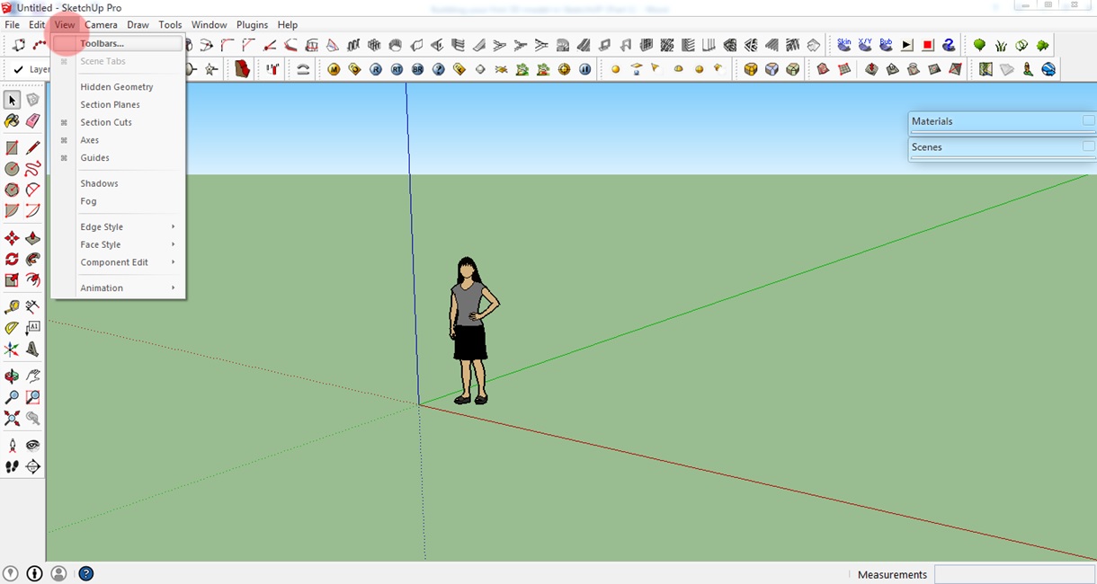
SketchUp has a lot of commands and tools that you can select from. On your first SketchUp workspace, you will see default toolbars on the upper part of your screen. Now click on View > Toolbars.
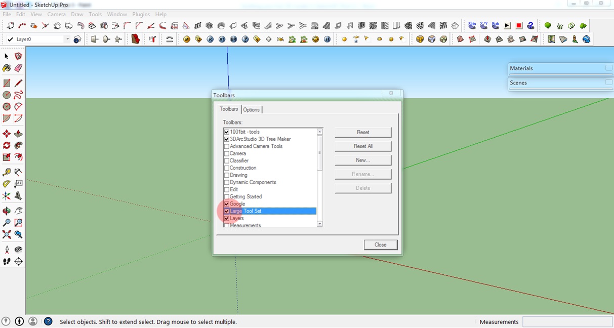
A window will appear with a list of toolbars. For this tutorial, we will use the Large Tool Set. This toolbar contains most of the tools you need to build a 3D model. Check the Large Tool Set. I recommend you uncheck the other toolbars to avoid confusion.
Step 4: The axes
SketchUp utilizes the Red, Green, and Blue axes in the workspace like any other 3D software. This allows you to view your work from different angles.
Also, SketchUp has a snapping feature that helps you align your lines or models along the different axes.
Now that we have our toolbar ready and see the three-dimensional space with its three axes in front of us, let’s start creating our first 2D shapes.
Step 5: Basic 2D Drawing – Lines, Rectangles, Circles
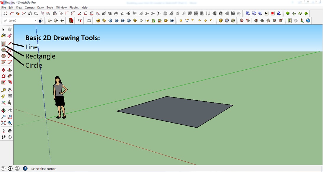
To get started, let’s draw Lines, Rectangles, and Circles. These are the fundaments of our (future) 3D models.
Drawing a line:
1. To draw a line, first, click the Pencil symbol on the toolbar or simply press L on your keyboard.
2. Click anywhere on your screen to assign the first point.
3. Drag the mouse to the desired location of the second point and click.
4. To specify the length (in this case I entered 5), simply type the value right after Step 2 and press Enter.
2. Click anywhere on your screen to assign the first point.
3. Drag the mouse to the desired location of the second point and click.
4. To specify the length (in this case I entered 5), simply type the value right after Step 2 and press Enter.
As you have probably already noticed, you can align any line to the Red, Green, or Blue axis of the workspace.
Drawing rectangles/squares:
1. To draw a rectangle/square, first, click the Rectangle icon on the left beside the pencil symbol or simply press R on your keyboard.
2. Click the desired location to assign the first corner of your rectangle/square.
3. Drag the mouse to the desired location for the opposite corner and click.
2. Click the desired location to assign the first corner of your rectangle/square.
3. Drag the mouse to the desired location for the opposite corner and click.
You can also enter the length and width of your rectangle/square: Enter the values after Step 2 and hit Enter on your keyboard. This part is a bit tricky. The first value you enter corresponds to the length/width along the Red axis and the second value corresponds to the length/width along the Green axis. Enter the values like this: 4, 4, Enter.
Drawing circles:
1. To draw a Circle, first, click the icon below the rectangle icon or simply press C on your keyboard.
2. Click the desired point to assign the midpoint of your circle.
3. Drag the cursor anywhere on the screen to make the circle and then click.
4. To specify the radius (i.e. radius = 2), simply enter the value right after Step 2 and press Enter.
2. Click the desired point to assign the midpoint of your circle.
3. Drag the cursor anywhere on the screen to make the circle and then click.
4. To specify the radius (i.e. radius = 2), simply enter the value right after Step 2 and press Enter.
Step 6: Movement Controls
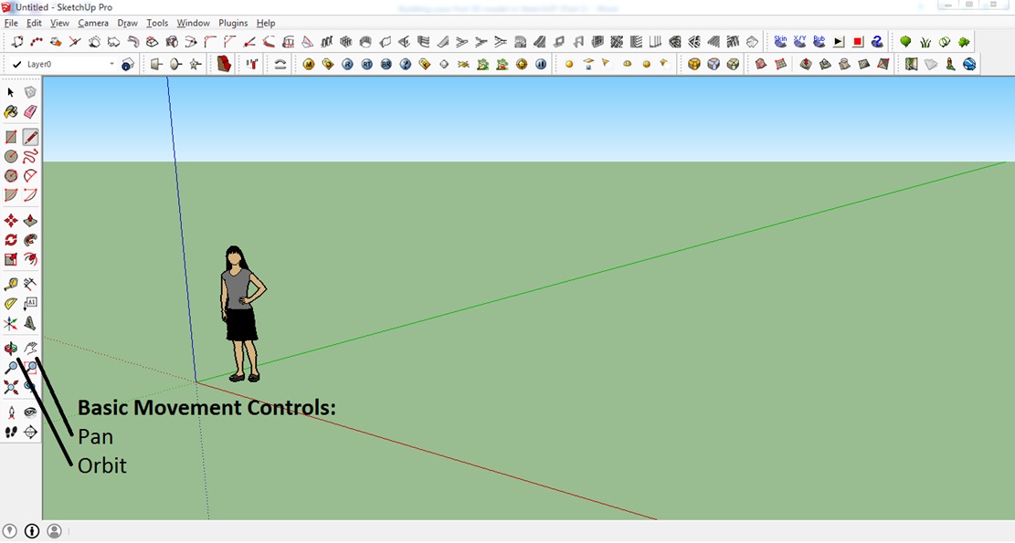
Let’s learn how to change our view with the basic movement tools of Pan and Orbit.
Pan:
1. To use Pan, click the icon or simply press H on your keyboard.
2. Click to set the origin, hold the mouse button and just drag. This will allow you to move your view.
2. Click to set the origin, hold the mouse button and just drag. This will allow you to move your view.
Orbit:
1. To use Orbit, click the icon on the toolbar or simply press O on your keyboard.
2. Click anywhere, hold and drag to rotate the whole view.
3. You can also use the mouse wheel to Orbit.
2. Click anywhere, hold and drag to rotate the whole view.
3. You can also use the mouse wheel to Orbit.
Step 7: Being on the Save Side – Undo and Saving
If you made a mistake simply click on Edit > Undo and you will be taken back to your previous step. You can also press Alt + Backspace for achieving this.
In order not to lose your progress, make sure to save your file from time to time. To do this, click File > Save or simply press Ctrl + S on your keyboard. Enter the filename and select the directory you want your file to be stored in.
Step 8: Making Your First 3D Object
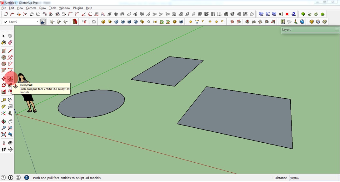
We’ve already created 2D shapes. Let’s turn them into 3D objects!
1. First, zoom in on of your 2D shapes using your mouse wheel button.
2. Click the Push/Pull icon on the toolbar or simply press P on your keyboard.
2. Click the Push/Pull icon on the toolbar or simply press P on your keyboard.
3. Hover your mouse cursor over the plane of the circle.
4. When you see the plane highlighted (i.e., when the plane shows a dotted texture on it), click on it and simply drag it upwards. Click the left mouse button again to set the height of your cylinder, cube or cuboid. Or type the height after the first click.
4. When you see the plane highlighted (i.e., when the plane shows a dotted texture on it), click on it and simply drag it upwards. Click the left mouse button again to set the height of your cylinder, cube or cuboid. Or type the height after the first click.
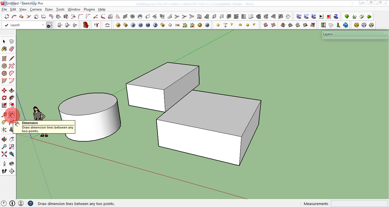
You will then see that the 2D shape converted into a 3D object. Congratulations! You have created your first 3D object!
Step 9: Dimension Tools
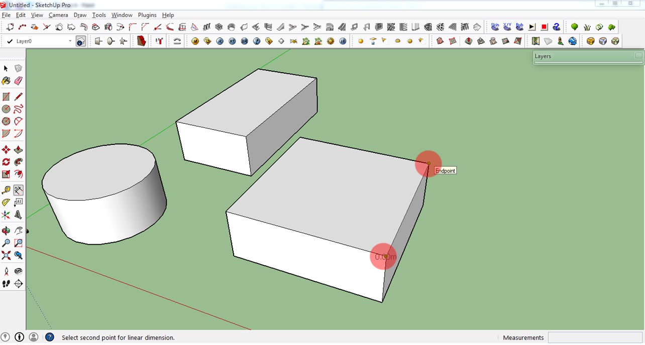
This tool allows you to check the dimensions of your model.
1. To use this tool, simply click the Dimension icon on the toolbar.
2. Next: Either click the starting point and then the end point of the line you want to measure. Or simply click the line. You will see the length of your line or object then.
2. Next: Either click the starting point and then the end point of the line you want to measure. Or simply click the line. You will see the length of your line or object then.
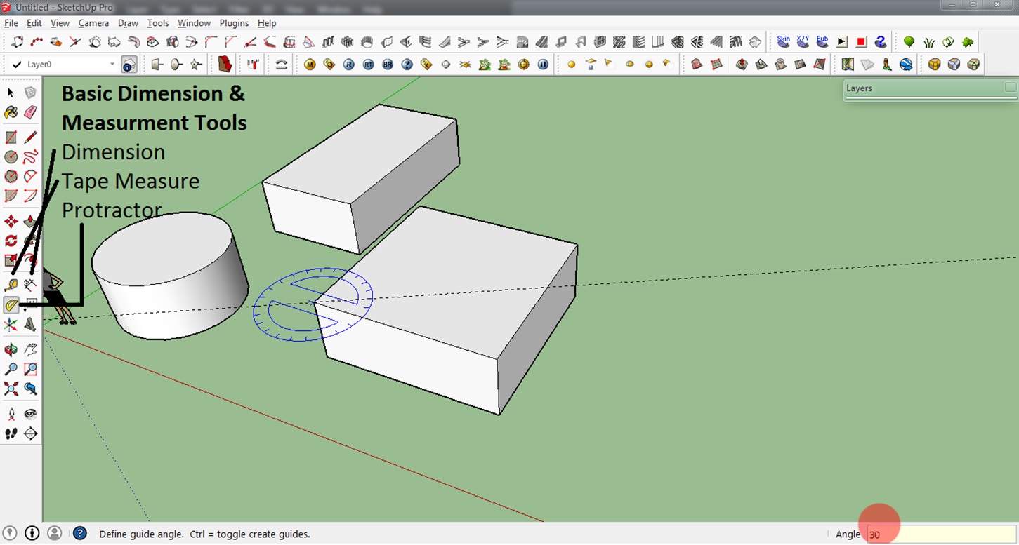
You can also use this Tape Measure Tool to measure distances more freely and the Protractor Tool to check different angles. The best way to learn these tools is by playing around with them. You can see the results of the Tape Measure Tool and the Protractor Tool in the lower right corner(see screenshot below).
Step 10: Moving and Maneuvering Objects
This tool is very easy to use:
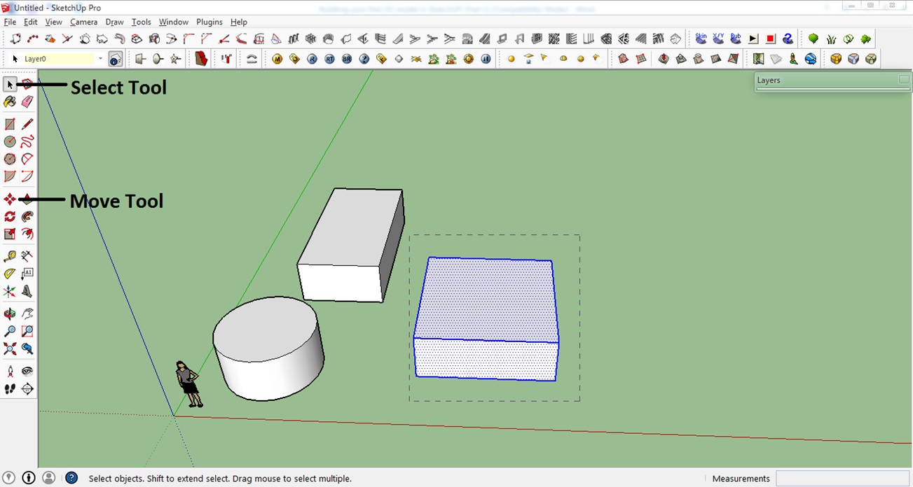
1. First select the object you want to move. Do this by clicking on the Select tool and ‘drawing’ a selection net around your object.
2. Click the Move tool or simply press M on your keyboard.
3. Click the selected object and drag it. Simply click again when you reached the desired location.
2. Click the Move tool or simply press M on your keyboard.
3. Click the selected object and drag it. Simply click again when you reached the desired location.
Step 11: Creating Copies of Your Object
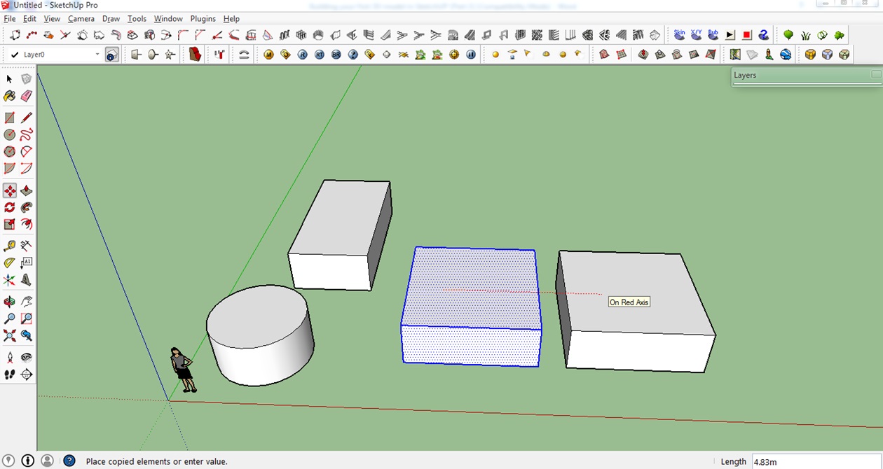
1. To create a copy of your object, select it again (as seen just above).
2. Press Ctrl on your keyboard to create a copy of the model.
3. Left-click again to place the copied model to the desired location.
2. Press Ctrl on your keyboard to create a copy of the model.
3. Left-click again to place the copied model to the desired location.
Step 12: Erase Tool
This tool works like a basic eraser: It erases lines or planes you have created.
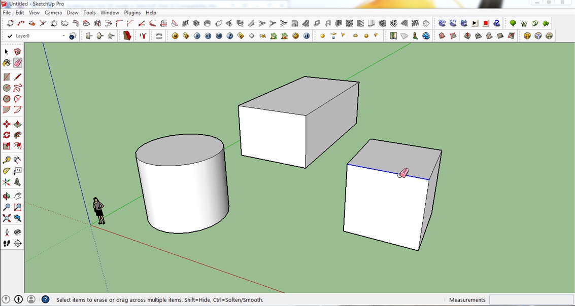
1. First is to click on the Eraser tool on the toolbar.
2. Once the eraser icon appears, click on the lines you want to erase.
(You can also select a line with the Select tool and then hit the delete button)
2. Once the eraser icon appears, click on the lines you want to erase.
(You can also select a line with the Select tool and then hit the delete button)
Step 13: Text
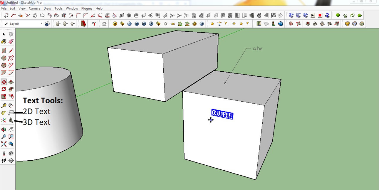
The 2D text tool allows you to calculate base areas of planes and to place labels. In the picture below it was used to label the object as a ‘cube’. The arrow indicates which object was labeled.
The 3D text tool actually creates the text as a 3D object that is part of your design. As always, it makes sense to simply play around with these two tools.
Step 14: Basic Cutting
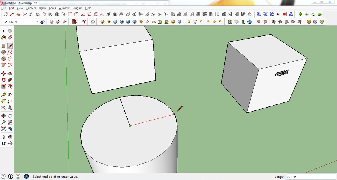
This tool allows you to cut or eliminate a section of your model. To show you how to use this tool, we use the cylinder.
1. Click on the Pencil tool on the toolbar in order to draw a line (we used this tool at the beginning of this tutorial).
2. For this tutorial, make a line on three points on the surface of the cylinder. First, from any point on the edge of the top surface of the cylinder. Second, a point to the center and third, a point across that aligns to the red axis.
2. For this tutorial, make a line on three points on the surface of the cylinder. First, from any point on the edge of the top surface of the cylinder. Second, a point to the center and third, a point across that aligns to the red axis.
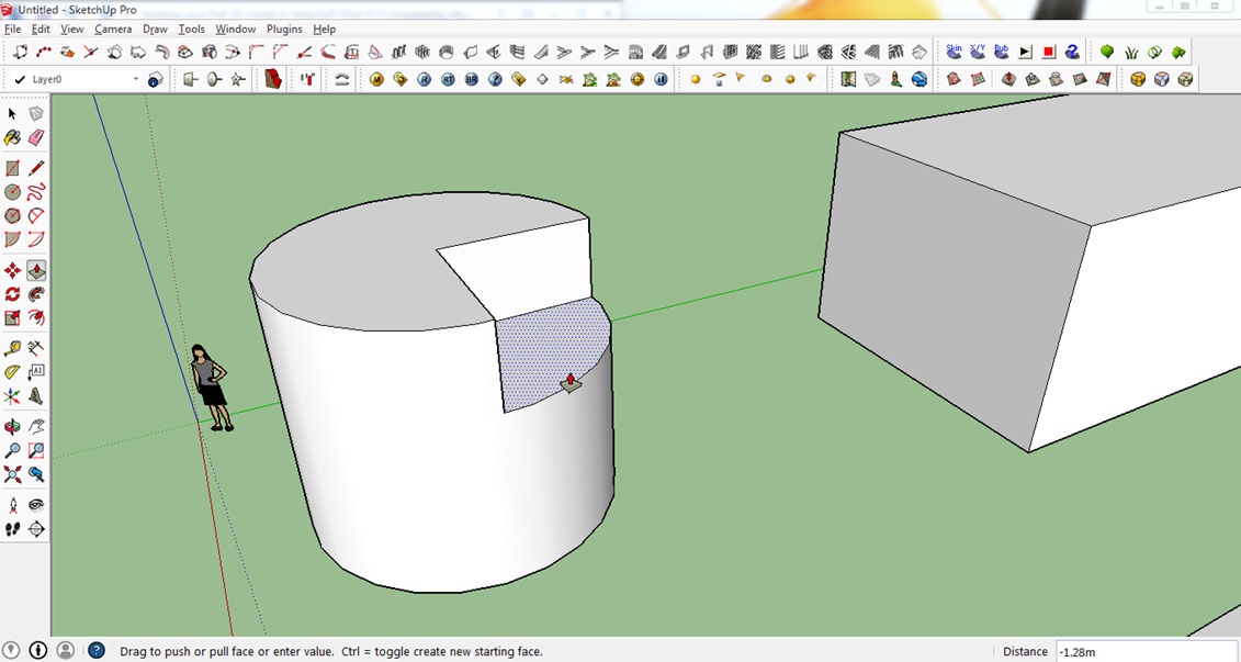
3. Click on the Push/Pull tool on the toolbar
4. Click on one-half of the top surface of the cylinder and push it downwards to create the cut and click to finalize.
4. Click on one-half of the top surface of the cylinder and push it downwards to create the cut and click to finalize.
What a nice, clean cut! Play around with this tool some more.
Step 15: Drawing an Arc
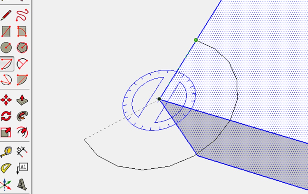
Besides lines, let’s try to draw with the Arc tool. It allows you to draw a curve. After selecting the tool, click on one of the corner points of a cube. Then click somewhere on one of its top axes and draw an arc. Sounds complicated? It’s easy once you try it!
After having drawn your arc, use the Pull/Push tool to cut this part off!
Step 16: Scaling & Stretching
This tool allows you to adjust your model accordingly or to the desired scale.
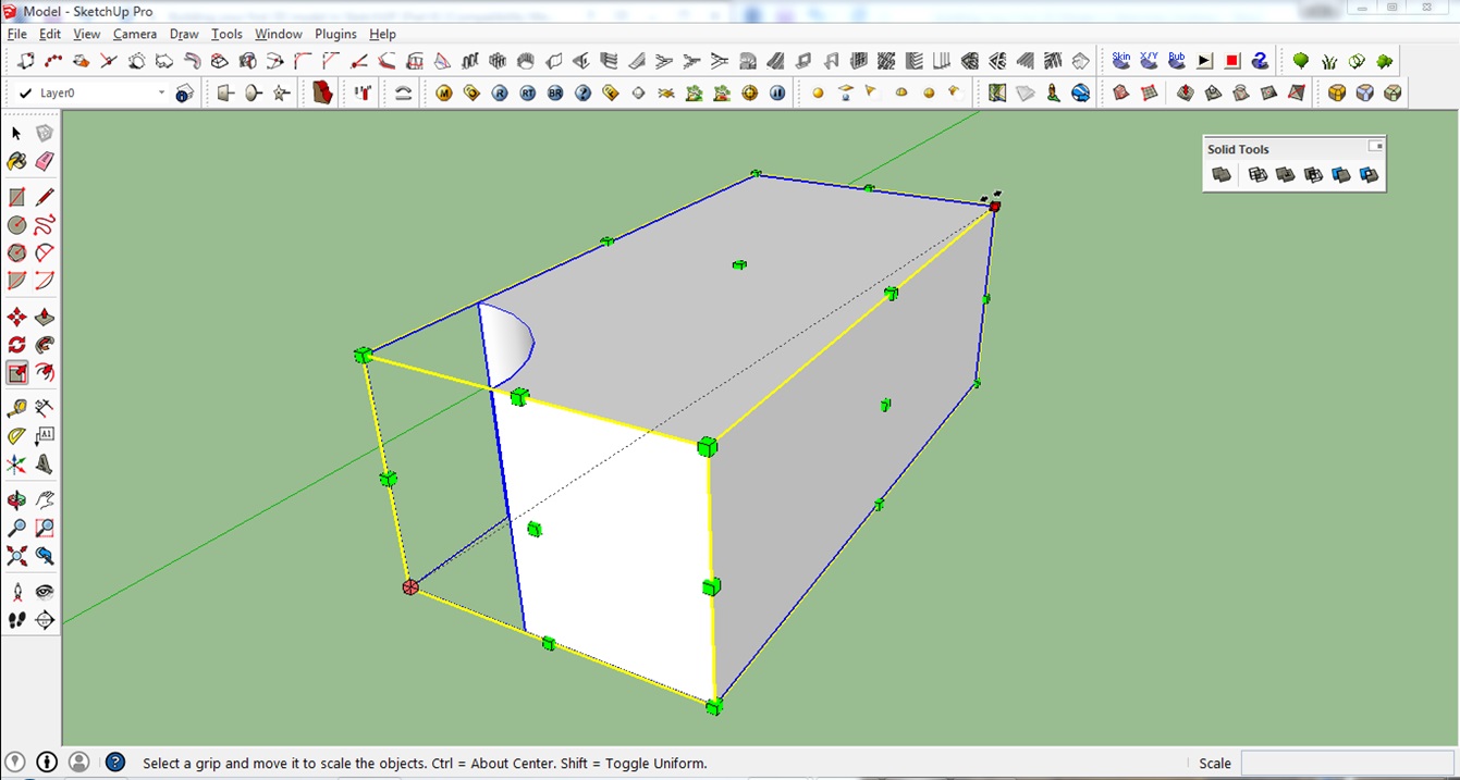
To use this tool, simply select your model first and click on the Scale tool on the right or press S on your keyboard. This will show you the different scaling points you can use. You can scale & stretch the object by clicking on the green dots that appear.
If you want to scale our model up or down while maintaining the ratio and proportion of our rectangular box (this is called uniform scaling) you need to click on one of the 8 corner points of the rectangular box.
You will see the value of your scaling in the lower right corner of the window. A value of 0.50 means you will be scaling your model down to 50%.
Step 17: Rotating
This feature is very useful when you experience orientation issues. This is when you have your model facing the opposite/wrong direction.
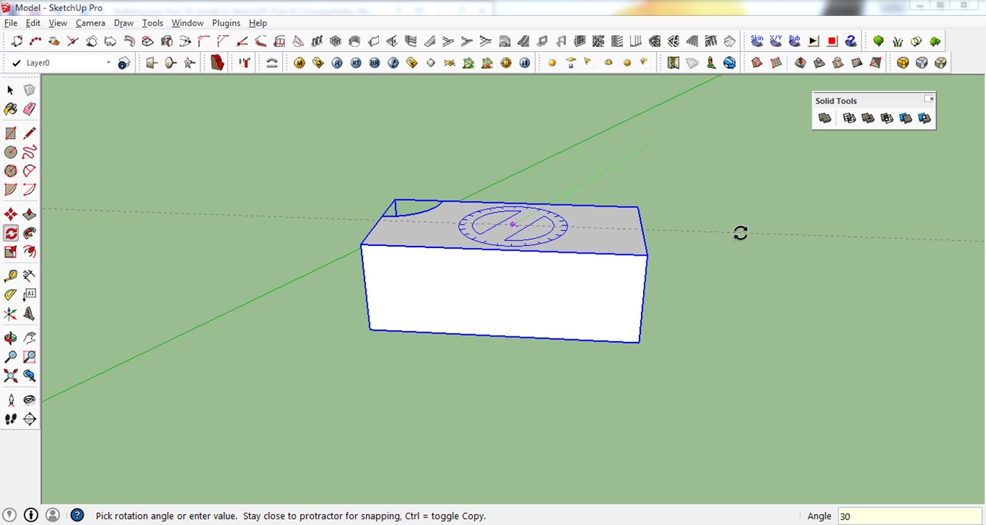
1. First select the model you want to rotate and select the Rotate tool or press Q on your keyboard.
2. Click on the center of the top surface of the rectangular box to set your axis. Extend your cursor towards the green or red axis to select the baseline of your rotation.
3. Rotate the model to the desired direction or simply input an angle value. In this case, we entered 30°.
2. Click on the center of the top surface of the rectangular box to set your axis. Extend your cursor towards the green or red axis to select the baseline of your rotation.
3. Rotate the model to the desired direction or simply input an angle value. In this case, we entered 30°.
Comments
Post a Comment